Rah AFzar Tarh
Company overview
Products
Contents
Training Videos
Free Stuff
Site Map
Contact us
Support services
Home page
|
- Displaying gradient between every two points based on TIN triangles when drawing lines or polylines
|
|
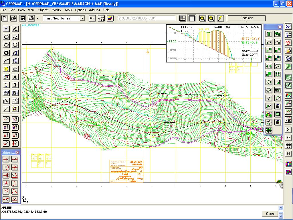
- Possibility to have two intervals when extracting profile and sections along a route, one for straight segments,
and the other for curved segments, and also possibility to extract points and sections at specific coordinates in addition to specific kilometers
|
|
|
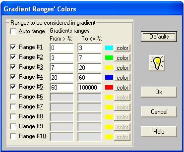
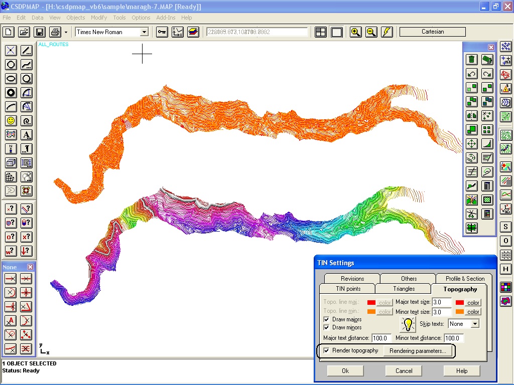
- Possibility to colorize TIN triangles based on the maximum gradient value in each TIN triangle and based on user specified gradient ranges and associated colors,
and also writing the gradient value in each TIN triangle in the direction of the maximum gradient when exporting to AutoCAD

- Possibility to specify gradient ranges and assign different colors to each range
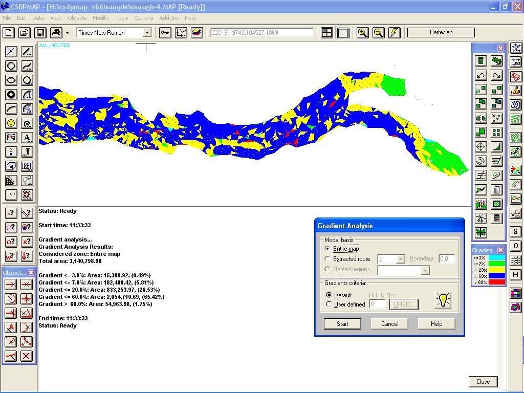
- A new dialog box for gradient analysis to calculate different gradient percentages for the entire map, one specified zone, or along an extracted route, and reporting area and percentage of every group of gradient in Status/Command panel
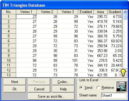
- Two new columns in TIN Triangles database dialog box for area and maximum gradient in each TIN triangle
- Possibility to check for angles of TIN triangles in triangulation to delete triangles with sum of two angles less than a specified value
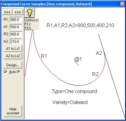
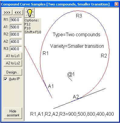
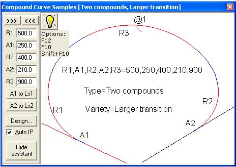
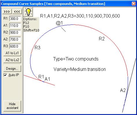
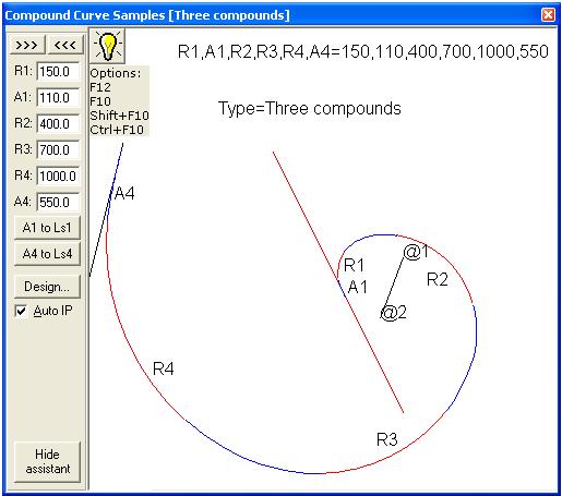
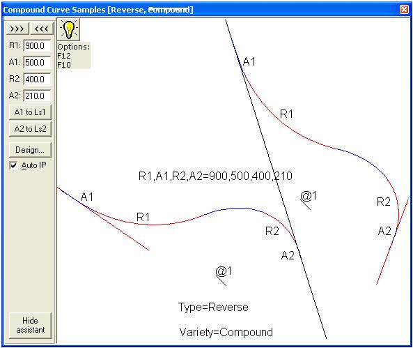
- Tools to design compound curves having intermediate spiral curves between two or more circular curves known as ESC curves
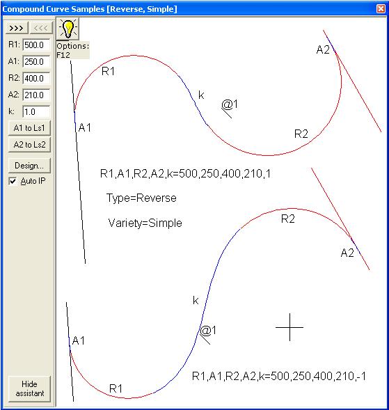
- Up to 10 different types of ESC curves included named as ESCRS (Reverse curve, simple), ESCRC (Reverse curve, compound), ESCOI (One compound, Inward), ESCOO (One compound, Outward), ESCTL (Two compounds, Larger transition), ESCTS (Two compounds, Smaller transition), ESCTM (Two compounds, Medium transition), ESCTH (Three compounds), ESCCI (Complex, Inward), and ESCCO (Complex, Outward)
|
| Back to Top
|
- A new tool named as ESC Assistant to design ESC curves helping to change parameters, drawing corresponding IPs, switching between simple and compound curves, mirroring the ESC curve, etc.
- A new object snap named as IP to snap to the ip point of an spiral object
- Possibility to have compound spirals (spiral between two circular curves) when using Route plan to draw a route based on IP specifications
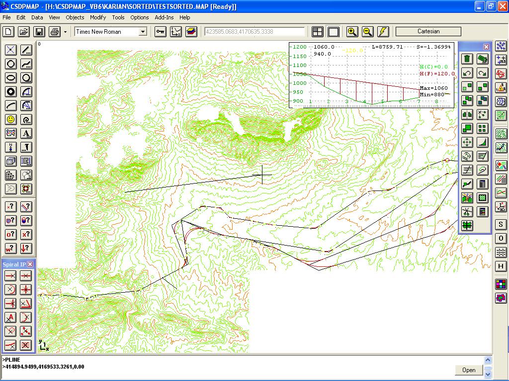
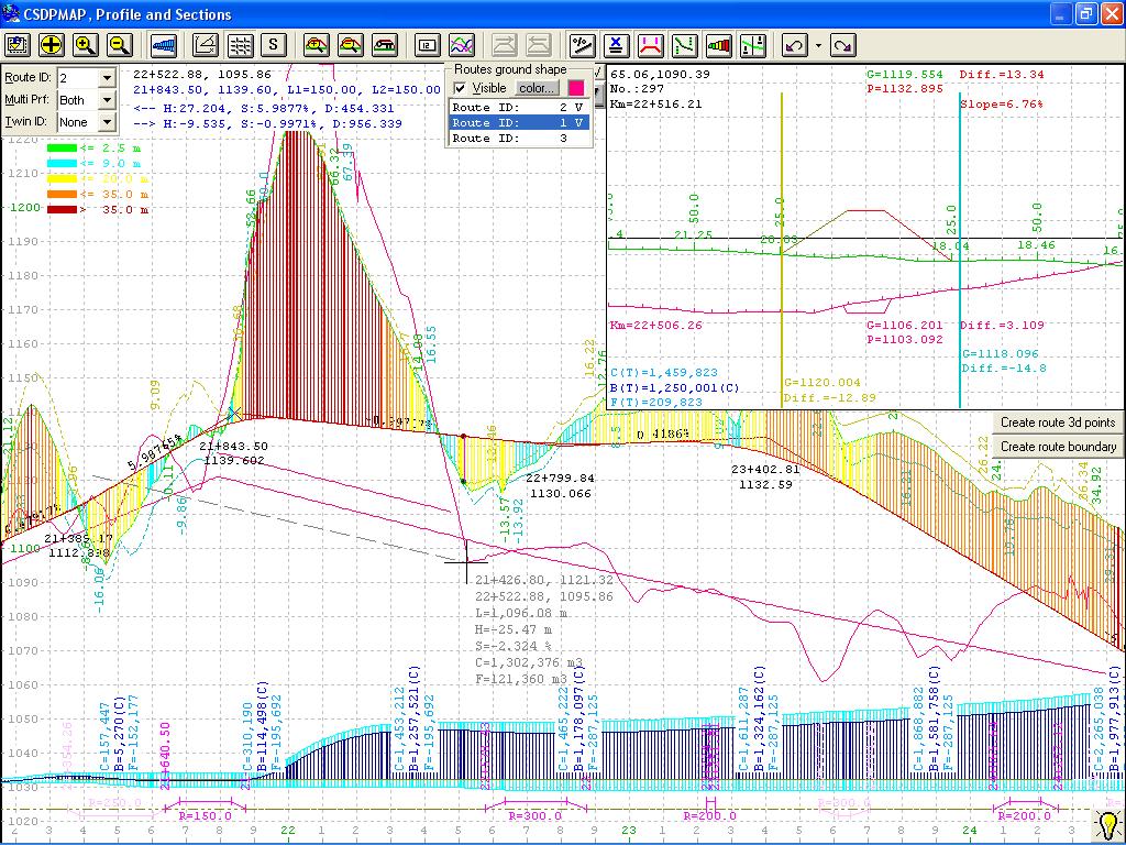
- New tools and options in Profiler window for displaying and working with longitudinal profile of an extracted route, such as displaying coordinates of IPs, horizontal curves information, height difference between ground and project along the route, and hatching profile based on elevation difference up to five elevation ranges specified by user along with corresponding associated colors
- Possibility to undo or redo the things done in Profiler window, such as IP creating, deletion, moving, Vertical curves editing, tunnels and bridges adding/removing/editing
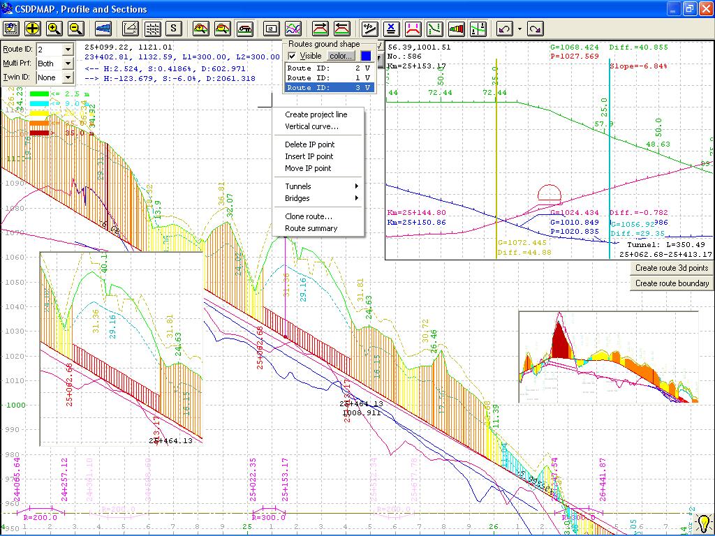
- Possibility to clone a route making a complete copy of a designed route with a new Route ID that can be modified later with new Clone route popup menu option in Profiler window
- Possibility to have a summary report for an extracted route in Profiler window with new popup menu option named as Route summary, and the information is reported in Status/Command panel
- Possibility to have up to 5 image clipboards in Profiler window to save an image of any portion in the Profiler window and moving to it when clicked
- When specifying coordinates of IPs in moving an IP in Profiler window, you can enter a coordinate using predecessor and or successor slopes with prefixes such as sp or ss, x or y, and also you can have relative coordinates for x or y coordinates
|
|

|
- Real time extracting profile along a segment drawn with line or polyline or arc commands, based on TIN surface or Contour surface and displaying the extracted profile as you move your mouse at the top right corner of the CSDPMAP window

- A new surface introduced named as Contour Surface that can be built based on topography data in form of contour lines when importing from AutoCAD files, without needing triangulation
- Possibility to use this new Contour surface as the surface model when extracting profile and sections along a route or when in grading feature, you need to specify a basic surface as the ground surface
|
- Possibility to divide Map objects in two horizontal or vertical images or to four images
|
| Back to Top
|
|
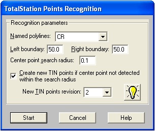
- Possibility to reorder unordered TotalStation surveyed points in such a way that is possible to read as cross section points in CSDP, CSDP+, CSDP-Pro applications software
- Possibility to render topography lines using colors spectrum just like Fractals surface and Contour surface
- A new panel named as Contour Surface Control Center (CSCC) for real time extracting, auto-design based on Contour surface
- Fast extracting profile tools in both FSCC and CSCC panels
- Possibility to convert Contour surface to Fractals surface
|
|
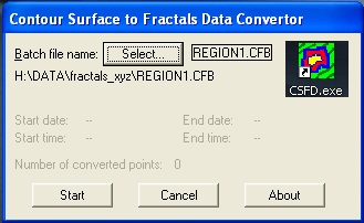
- A new external utility named as CSFD Converter for converting Contour surface to Fractals surface in multi-million points projects which required multiple computers
| |
- Possibility to see and check maximum allowable slope when design longitudinal project line of a route in Profiler
- Possibility to have polylines with segments in different colors by introducing a new technique named as Vertices Colors
- Possibility to extract profile and sections along a route at intersection points of route with TIN triangles instead of extracting in specified intervals
|
| Back to Top
|
|
One of the most important features in version 9.00 of CSDPMAP is capability to design interchanges.
|
|
Below the method for designing interchanges in CSDPMAP is described:
- Drawing Plan, Phase one; drawing of all main routes and ramps or loops
- Extracting profile along each route for routes geometries
- Reading surveyed points for each route with auto-correction possibility
- Drawing Plan, Phase two; drawing of bands for each route and naming each route and its bands separately
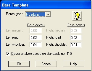
- Defining a base template for devers (super elevations) in direct parts of routes
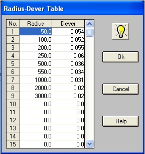
- Defining required devers (super elevations) for different radiuses of horizontal arcs
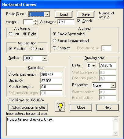
- Defining and checking proration lengths of horizontal curves in Horizontal Arcs dialog box
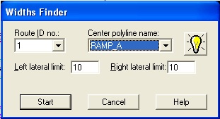
- Using Widths Finder tool to auto-calculate widths of different bands in each route at left and right sides
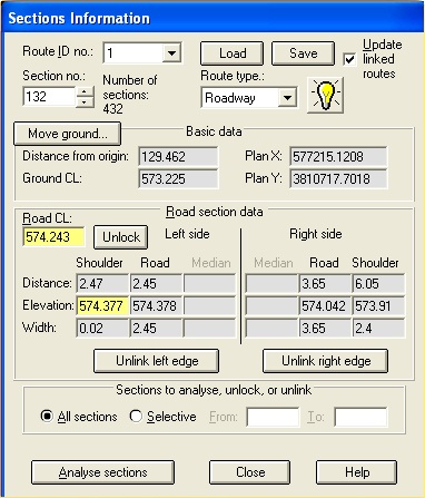
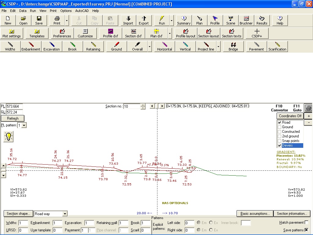
- Checking calculated widths in Sections Information dialog box and analyzing cross section
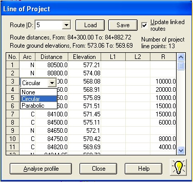
- Defining project lines of main route in Project Line dialog box
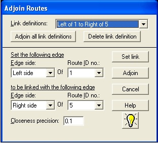
- Using Adjoined Routes tool to auto-derive the related fixed parts of edges in ramps and loops
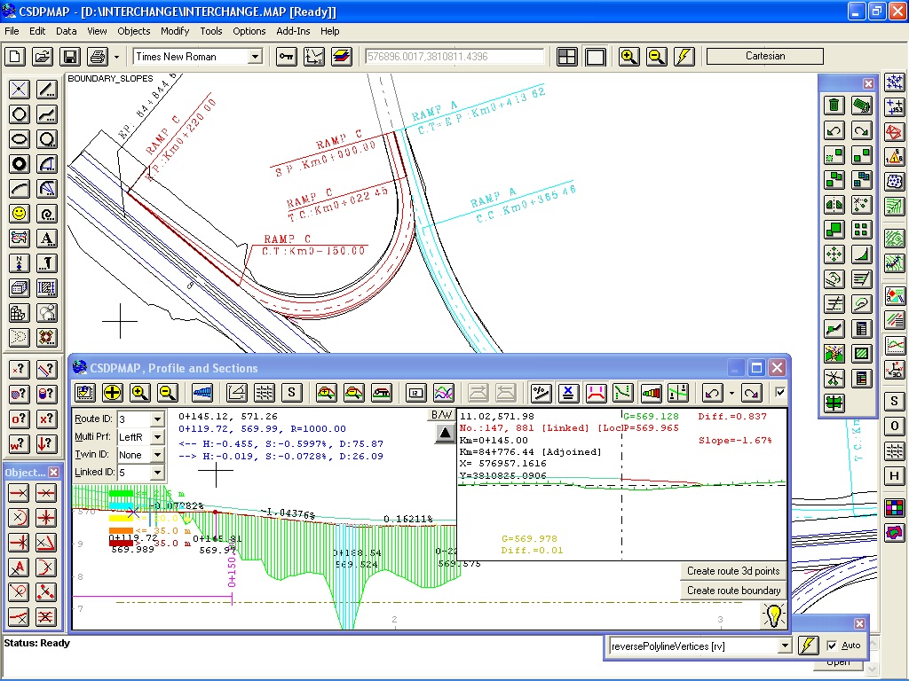
- Using Profiler to check the related parts and to design project lines for ramps and loops in free parts
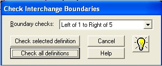
- Using "Check Boundaries" tool to check for overlapping boundaries of ramps and loops and main routes and removing those overlaps
- Exporting resulted project lines and cross sections to CSDP+ or CSDP-Pro for finalization of cross section analysis and volumetric calculations
|
|