- A new embankment case named as D for height consideration at center instead of at edge
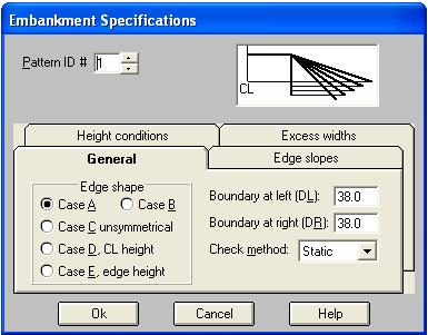
- A new embankment case named as E for consistency with Standards 161
- Possibility to combine different area and length items to create new formulas
- Possibility to display distinguished section names, and zones in Profile and Sections mode
- Possibility to define project lines graphically in Profile and Sections mode with two new methods named as x,ss and sp,ss
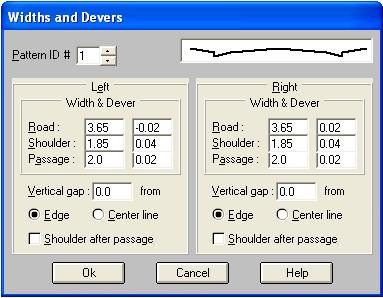
- Possibility to place shoulder band after passage band in Urban template
- Two new algorithms to construct embankment edge slopes
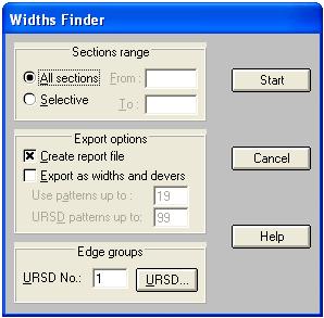
- Possibility to combine URSD patterns with normal Widths and Devers pattern to create new section templates
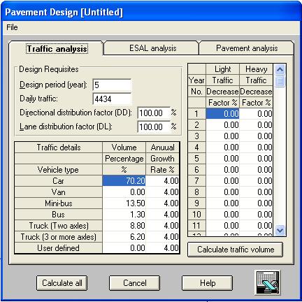
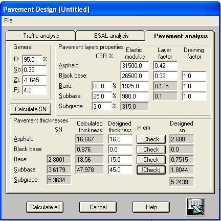
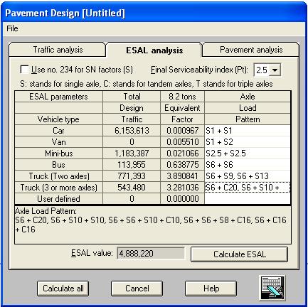
- Pavement design by Standards 234, and AASHTO standards
|
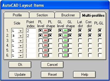
- Possibility to have multi-lateral profiles at points corresponding to specific points in cross section template along with elevations, corrected distances, lateral distance, etc.
- A new profile layout for pipe-line projects
- Possibility to model different types of serpentine curves in Automatic Plan
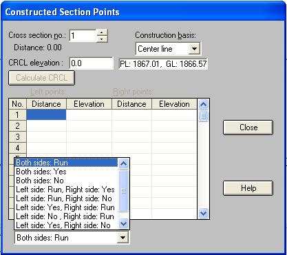
- Possibility to have longitudinal profiles of constructed sections, and three project line patterns at the same time with normal longitudinal profile
|
| Back to Top |
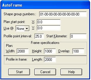
- A new Auto-frame feature to create plan-profile frames for existing plan automatically
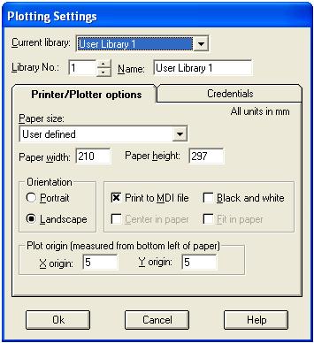
• Direct plotting/printing of cross sections, longitudinal profiles, and plan-profile
- Possibility to create MDI and PDF files of cross section shapes, longitudinal profile, and plan-profile
- Possibility to export circle and spiral objects as Polyarc objects to AutoCAD
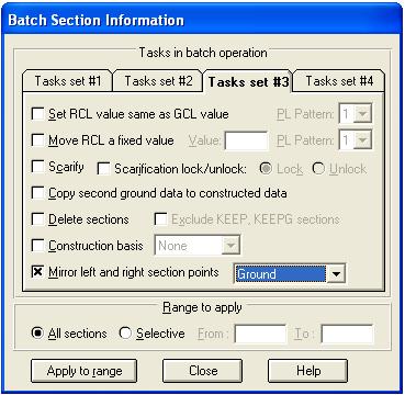
- Possibility to mirror left and right sectional points in cross sections
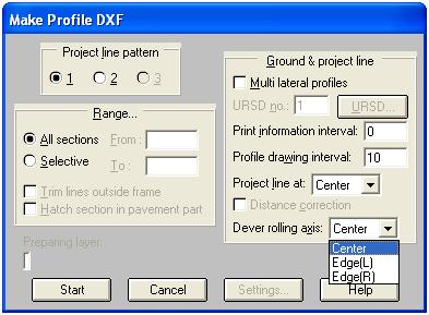
- Possibility to specify a rolling axis at center, left edge or right edge to adjust devers (lateral slope) with respect to it
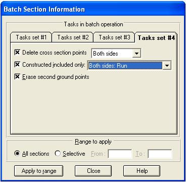
- Possibility to adjust Included part only for constructed sections at left, right or both sides
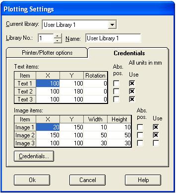
- Possibility to have customized separated formula files CSDPCALC.CFG for each project file
|
| Back to Top |
- Possibility to create customized CSDPCALC.CFG files for each project separately.
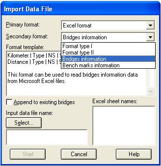
- Possibility to import bridges and bench marks information from Microsoft Excel files.
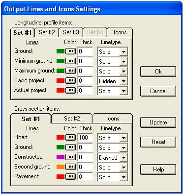
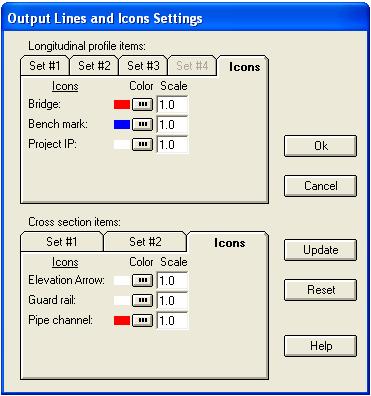
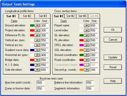
- New options to control properties of texts and lines of different items in longitudinal profile and cross section shapes, such as color, line thickness, font size, etc.
|
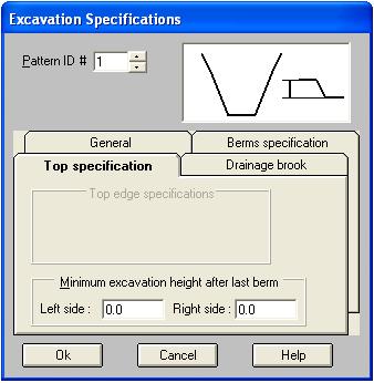
- A new item in Excavation Specifications to control the minimum height of the last berm at each side.
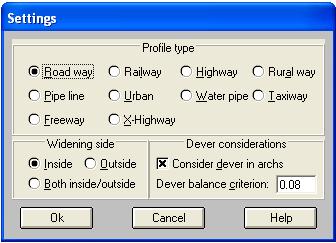
- Possibility to consider widening side due to horizontal curves for both sides of the center line at the same time
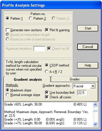
- Possibility to specify different categories of grades for gradient analysis
- Possibility to print x,y coordinates of the center line of a route in cross section shapes
- Possibility to erase second ground points in Batch Section Information dialog box.
- Possibility to specify a slope value as a URSD point, when merging URSD information with normal templates, to have dynamic point coordinates
|
- Possibility to have a summary of results of volumetric operations for printing purposes.
- A new output xyz format compatible with TotalStation.
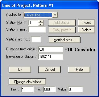
- Possibility to change all project line elevation in Project line dialog box
- Possibility to view the three patterns of project lines at the same time in Profile and Sections mode.
|
|
- Possibility to adjust and modify project line graphically for Pipe-line projects in Profile and Sections mode.
|
| Back to Top |
|
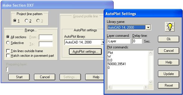
- The SCRIPT file required to print cross section shapes automatically in AutoCAD using one script command, now is created when making the DXF of cross sections.
- Possibility to choose a printer when printing results or project data.
- Creating project file backups now is done automatically
|
- Possibility to interpolate dever based on widths and devers patterns just like width of bands when cross sections are not located in a horizontal arc.
|
- Displaying of devers on cross section shapes in Normal mode or Profile and Sections mode.
|
- Three methods for gradient analysis named as Piecewise, Renewal, and Fractal, and possibility to specify a boundary lateral limit
|