Rah AFzar Tarh
Company overview
Products
Contents
Training Videos
Free Stuff
Site Map
Contact us
Support services
Home page
|
- Possibility to define band width (interval) in calculation of cross sections area and length items
- Possibility to use distance from origin (kilometer) of sections in Overall Section Information dialog box, in addition to of cross
section numbers for defining a range
- Possibility to use Auto button in Bruckner mode for calculating of distribution lines lengths
- Possibility to read data files of TotalStation surveying cameras with FeedBook format
- Possibility to export routes data in a format applicable to FeedBook handhelds
- Possibility to define explicit patterns for cross sections in Section Analyser region in normal mode
- Possibility to export grid elevations data to Microsoft Excel, and import from it
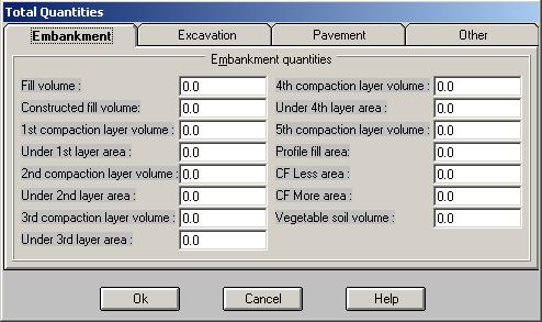
- Possibility to define unsymmetrical embankment conditions for left and right of route
- A new cross section template known as Freeway type is added
- Possibility to sketch pavement line in cross section shape with a dashed pattern
- Possibility to read topography polylines data from AutoCAD, and converting it to xyz point coordinates
- Possibility to design spiral curves based on radius and spiral length, in addition to radius and spiral parameter
- Possibility to draw routes plan automatically based on a data file containing IP(s) coordinates and spiral curves radius and length,
in addition to spiral curves radius and spiral parameter
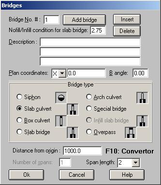
- Possibility to alter the criterion for identifying infill and no fill bridges
|
| Back to Top
|
- Possibility to export ground and road section points data to Microsoft Excel
- Possibility to extend ground line at edges (horizontal, same slope, average slope)
- Possibility to insert or delete ground section points in the middle of the points in Ground Section Points and URSD dialog boxes
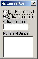
- A new tool known Convertor is added to convert nominal and actual distances from origin (kilometer) and vise versa
- Possibility to define section zone as Normal, in Tunnel, or in Bridge
- A new longitudinal profile layout is added in printing phase known as M layout
- Possibility to print cross section table containing coordinates of ground and road points for every cross section
- Possibility to insert or delete horizontal arcs in the middle of the arcs in Horizontal Arcs dialog box
- Possibility to read text entities insertion points from AutoCAD, for extracting xyz coordinates of points
- Possibility to create Windows Media Player files (avi) from walk through bitmaps in the 3D Scene mode
- Possibility to adjust and filter xyz points while sorting
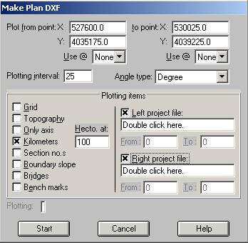
- Possibility to define hectometers distance apart in Making plan dxf for sketching routes plan shape
- Possibility to include embankment and excavation lines (boundaries) in Making plan dxf for sketching routes plan shape
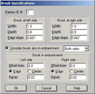
- Possibility to define ditch (brook) lateral distance in embankment condition and the required lateral slope (dever)
- Possibility to define height of rail, traverse and the thicknesses of ballast, sub ballast layers in Railway template type
- Bridges descriptive lines increased from one to three 30 characters length lines and possibility to define inclination angle of the
bridge axis from the route axis
- Possibility to find coordinates of bridges and bench marks automatically from the plan shape of the route comparing to the distances
from origin (kilometers) of bridges, bench marks
- Possibility to edit profile and cross section points coordinates in View mode (Profile and Sections mode)
- Possibility to sketch bridges, bench marks and section names (no.s) in routes plan shape
- A new very simple format for ground section points data entering is added
|
| Back to Top
|
- Possibility to design serpentine curves
- Possibility to draw and sketch longitudinal profile of minimum ground elevations of every section
- Possibility to design serpentine curves
- Possibility to draw and sketch longitudinal profile of minimum ground elevations of every section
- Possibility to define two new criteria in Pipe line analysis for maximum allowable angle difference of every two consecutive project line segments and pipe line segments
- Possibility to sketch routes plan coordinates at axis and specified boundaries in making plan DXF of routes plan shape
- Widths and Devers patterns increased to 20 patterns
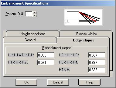
- Possibility to define five different slopes, 4 height conditions, and 4 different excess widths for edge shape in embankment
condition, according to standards no. 106 of Ministry of Roads and Transportation
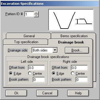
- Possibility to define drainage ditches (brooks) at the upstream in excavation conditions
- Zoom and Pan facilities in plan mode are added
- Possibility to select text objects in plan mode based on the sizes
- Possibility to define true sizes for text objects in plan mode corresponding to Small, Normal, Large, Very large and Extra large sizes
- Many features are added in Bruckner mode to deal with bruckner diagram and distribution line analysis
- Possibility to interpolate new points based on the existing points, while reading the data from AutoCAD topography files
|
| Back to Top
|
- Possibility to define two terrain models as the natural ground shape, and calculation of the cut and fill volumes between these two in
a specified region
- Many features added regarding site preparation and leveling projects
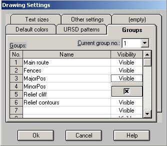
- Possibility to name groups in plan mode, which can be assumed as counterparts of layers in AutoCAD (while importing or exporting the
group names are converted to layer names and vise versa)
- Possibility to set text sizes of different items in routes plan shape while making plan DXF
- A new tool known as Annotate is added in plan mode for annotation of different drawing objects
- A new inquiry tool is added in plan mode for calculation of a route total length
- A new object known as Frame is added in plan mode for making plan-profile sketches
- Possibility to define frames manually based on the insertion point, width and length of the frame, and the escapement value
- Possibility to use AutoFrame tool for creation of Frames based on the specified route
- Possibility to convert line objects in plan mode to Frame objects
- Possibility to sketch plan-profile layouts with a new added option in menu (Making plan-profile dxf)
|
|