Rah AFzar Tarh
Company overview
Products
Contents
Training Videos
Free Stuff
Site Map
Contact us
Support services
Home page
|
- Possibility to have customized separated formula files CSDPCALC.CFG for each project file
- Possibility to import bridges and bench marks data from Microsoft Excel files
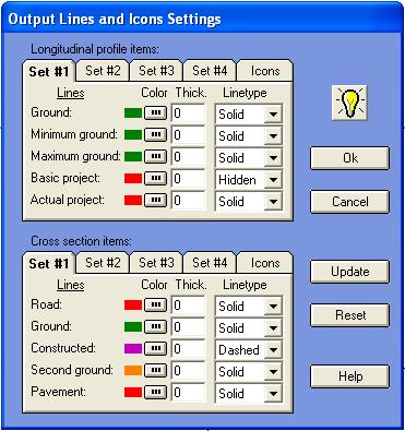
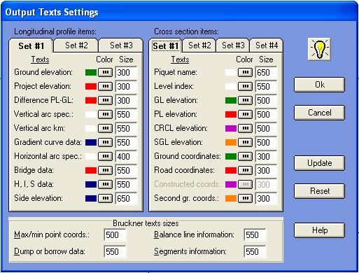
- New items to control color, size, thickness etc. properties of different items in cross section shape, longitudinal profile when printing/plotting
- Possibility to save as a project under earlier versions of CSDP+ application software (9.51, 9.56, 9.57, 9.60, 9.61, 9.62, 9.65, 9.66, 9.75)
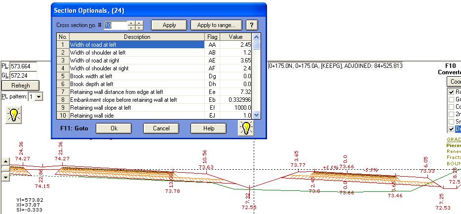
- New items as ‘Section’s Optionals” to control different parameters of a cross section template
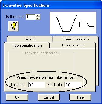
- A new option to control minimum height of the last berm (stair) in excavation condition
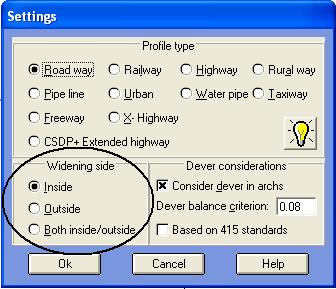
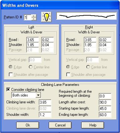
- Possibility to have widening at both sides of the road at the same time
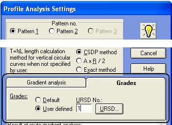
- Possibility to define new range of gradients in form of percentages groups for “Route Gradient Analysis”
- Possibility to create new bridges and to edit or delete existing bridges graphically in “Profile and Sections” mode
|
|
- Possibility to have x, y plan coordinates of center line of route in every cross section shape
- Possibility to delete second ground information in “Batch Section Information” dialog box
- Possibility to have dynamic points in URSD points definition to be combined with basic points derived from normal section templates
- Possibility to select a printer when printing results or project data
- A Backup for a project file is automatically created when you open a project file.
- Possibility to interpolate devers like widths when calculation of devers based on horizontal curves is disabled
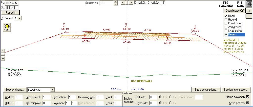
- The dever value is shown on the cross section shape in Normal mode and Profile and Sections mode.
|
| Back to Top
|
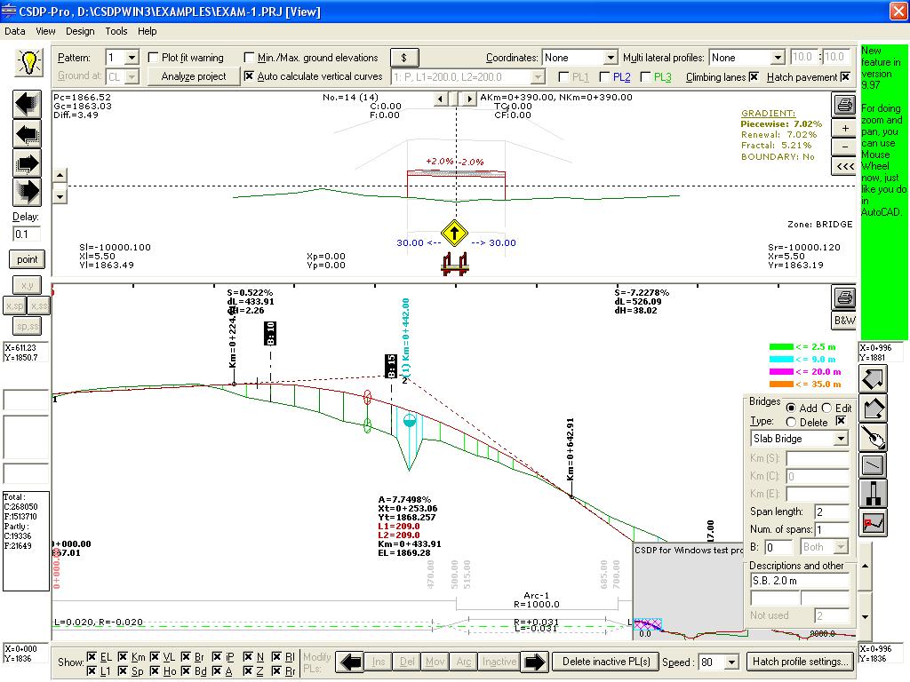
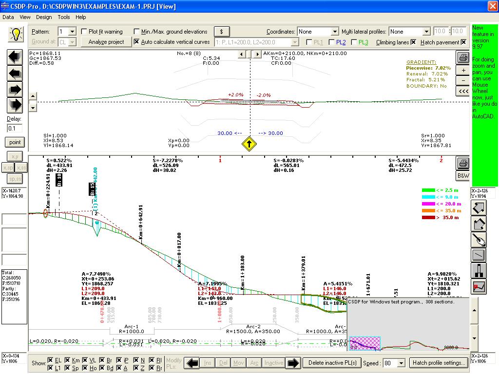
- Three methods of calculation in gradient analysis named as Piecewise, Renewal, and Fractal, and possibility to specify a boundary limit in gradient analysis
- Displaying sectional gradient values based on the three methods of Piecewise, Renewal and Fractal on cross section shape in Normal mode, and Profile and Sections mode
- Possibility to specify a section name in sixth column when using TotalStation format to import ground data
- Possibility to have excess width for guard rail when using Case B in embankment
- Possibility to interpolate new cross sections when analyzing longitudinal profile for starting and ending points of tunnels, galleries and special bridges
- Possibility to delete newly interpolated cross sections for starting and ending points of tunnels, galleries, and special bridges in Batch Section Information dialog box
- Possibility to export ground data in Chainage format
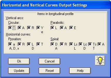
- Possibility to include or exclude items to be printed for horizontal and vertical arcs information
- Possibility to use automatic scale as the second scale for cross section shapes and longitudinal profile
- Possibility to have negative retraction lengths for horizontal arcs with proration
- New profile layouts for pipe line projects
- Displaying curves information and devers information for horizontal arcs in Profile and Sections mode, same as in DXF output, and also reporting and marking inconsistent arcs in a list
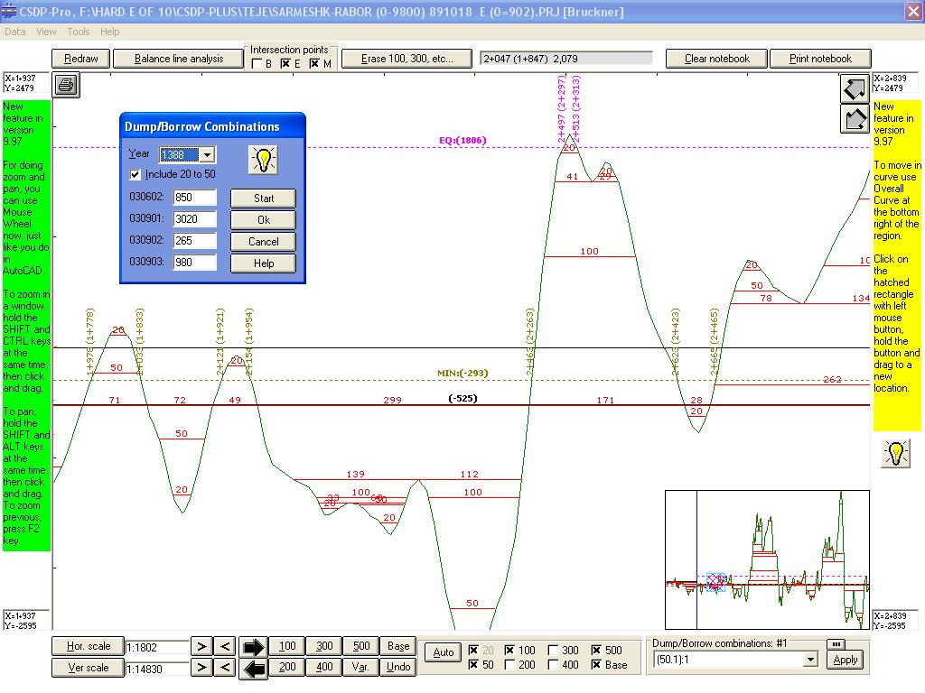
- New tools in bruckner mode for moving around and focusing on an extreme point
- Displaying kilometer (distance from origin) of intersection points of balance lines (minimum, equal) with bruckner curve
|
|
| Back to Top
|
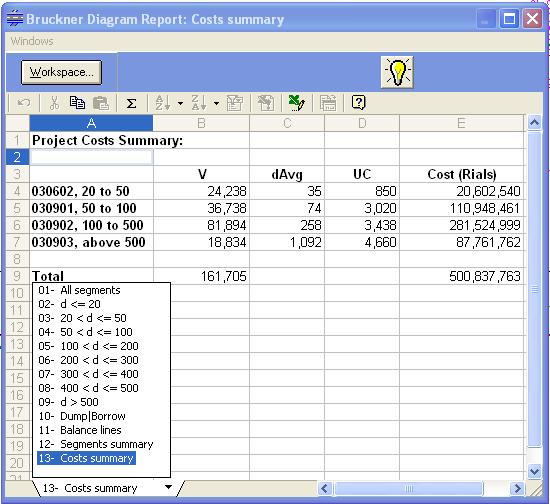
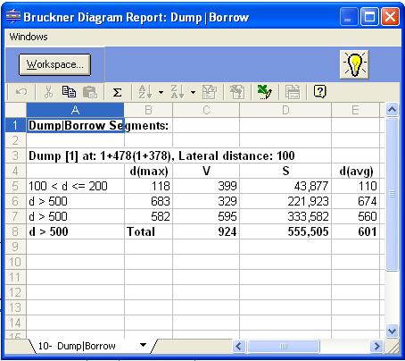
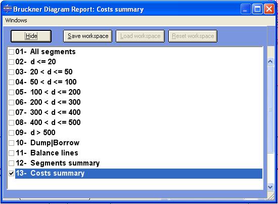
- Bruckner report for all segments, categorized, summarized, and between each two dump/borrow definition, volumes, costs
- Possibility to combine different dumps and borrows, for 10 dumps/borrows up to 1024 combinations and sorting them to find the least cost case
- Possibility to move back and forth quickly in Results mode for very large projects having thousands of cross sections
- Tools to design compound curves having intermediate spiral curves between two or more circular curves known as ESC curves
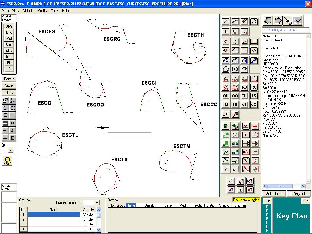
- Up to 10 different types of ESC curves included named as ESCRS (Reverse curve, simple), ESCRC (Reverse curve, compound),
ESCOI (One compound, Inward), ESCOO (One compound, Outward), ESCTL (Two compounds, Larger transition), ESCTS (Two compounds, Smaller transition), ESCTM (Two compounds,
Medium transition), ESCTH (Three compounds), ESCCI (Complex, Inward), and ESCCO (Complex, Outward)
- A new object snap named as IP to snap to the ip point of an spiral object
- Possibility to have compound spirals (spiral between two circular curves) in Automatic Plan
- A new property for Extended highway cross section templates to join the inner edges of the two sides (when PL are different) with a straight line and one slope instead of normally two lines having two different slopes
- Displaying coordinates of intersection points of ground and project in every cross section on cross section shape in Normal mode and Profile and Sections mode
- Possibility to specify heights in Case B of embankment to be considered from the bottom instead of the top
- Possibility to use Shift/Reverse project in Extended highway profile type
|
| Back to Top
|
- A new method for project line analysis of pipe line projects named as Enhanced Pipe Algorithm
- A new method for interpolation of new ground section points among existing sections points regarding requirements of pipe line segments in pipe line projects
- Possibility to have asphalt shoulder band in addition to the shoulder band in Freeway profile types
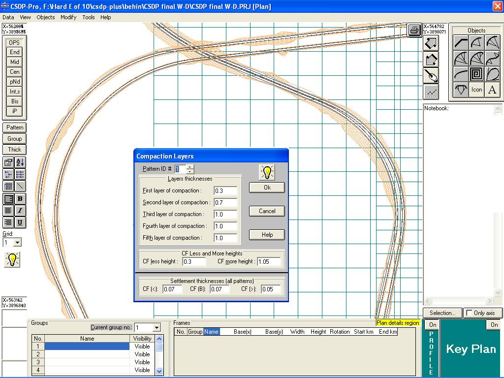
- Possibility to display and print of different layers of pavement using different hatches and colors
- Possibility to display and print boundary slopes in plan for Extended Highway profile types
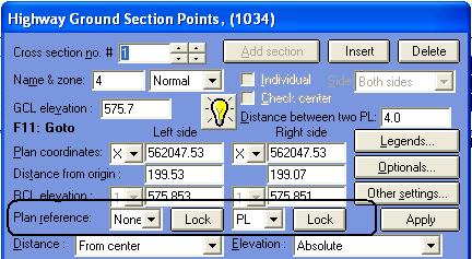
- Possibility to define Plan Reference point with options of “None”, “Default”, “CL” and “PL” for each of the left and right sides of the route in Extended Highway profile type
- Possibility to import Overall Section information data from Microsoft Excel files
- Possibility to import Optionals Section information data from Microsoft Excel files
- Possibility to import RCL and PCL elevations in pipe line projects from Microsoft Excel files
- New tools for editing project line in pipe line projects in Profile and Sections mode
- New optionals for combining different patterns of pavement layers as composite pavements named as “2A”, “2B”, “2C”, “2D”, “3A”, “3B”, “3C”, “3D”…”9A”, “9B”, “9C”, “9D” in addition to “LA”, “LB”, “LC”, and “LD” in previous versions
- Analysis of climbing lanes for defining required extra band in zones of climbing lanes

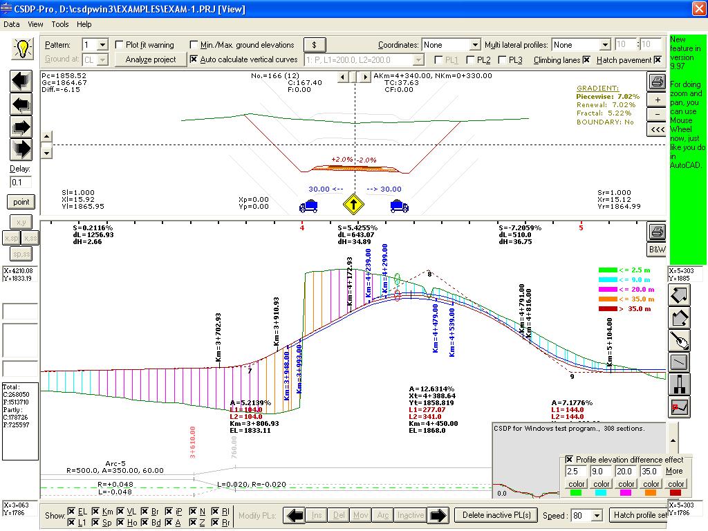
- Displaying and printing of climbing lane zones in longitudinal profile shape of the route, and displaying climbing lane icon in cross sections
- Possibility to have retaining wall in excavation condition in different segments of an excavation part such as in berms (stairs) etc.
Back to Top
- Possibility to hatch longitudinal profile shape with different colors depending on the elevation difference between project and ground at center line in Profile and Sections mode
- Undo/Redo capability in Profile and Sections mode for all the tasks that can be done in this mode
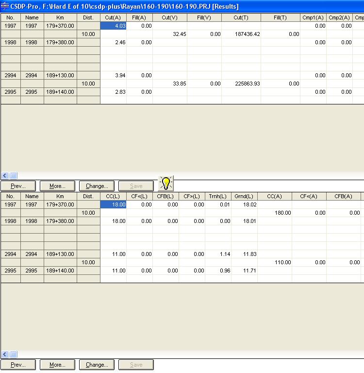
- Introducing two height conditions instead of one in previous versions to distinguish CF lengths in three parts unlike previous versions that it was two, named as CF<, CFB, and CF>
- Possibility to specify the settlement thickness individually for each of the three CF lengths
- Introducing Rolling Axis in a cross section that can be at left, center or right of cross sections for designing purposes required in projects dealing with ramps and loops
- Possibility to print x coordinates in cross sections measured from PL instead of CL in Extended Highway profile type
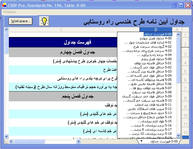
- Standards no. 196 for rural roads included along with radius-dever tables that will be used for Rural profile types
- Possibility to change basic design speed along a route with new “GE” optionals flag
- New optionals for specifying side and number of berms (stair) in excavation conditions
- New optionals for specifying parameters of each berm (stair) individually for left and right sides named as “1f”, “2f”, “3f”…, “1g”, “2g”, “3g”…, “1h”, “2h”, “3h”…
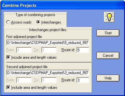
- Possibility to combine cross sections derived from multiple projects for creating a combined cross section in interchanges, with regarding to new feature as “Interchange Design” in CSDPMAP application
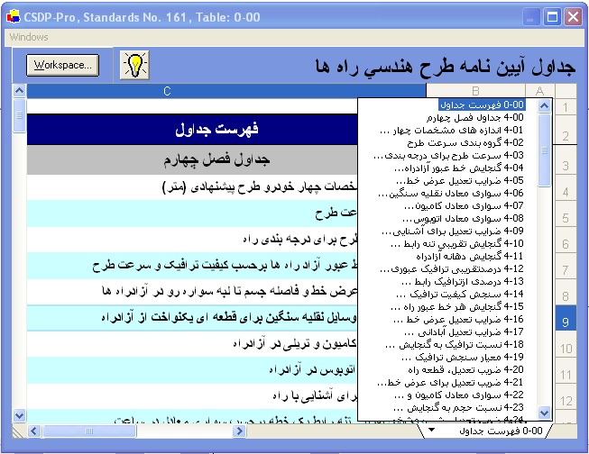
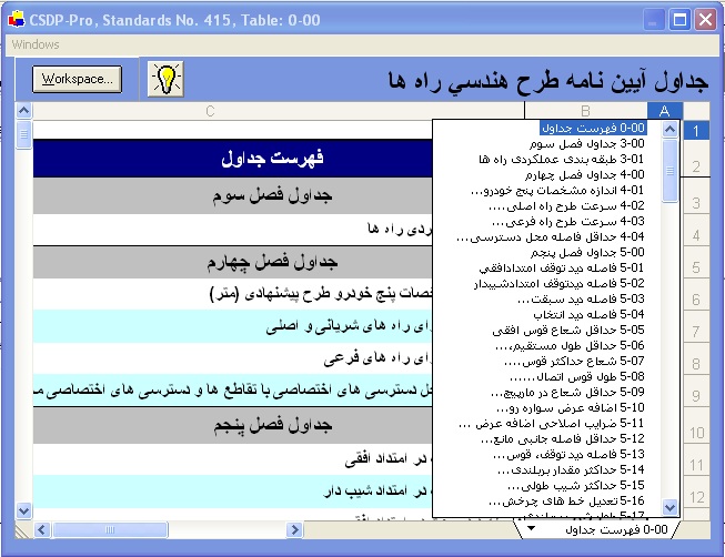
- Standards no. 415 of Highways and Roads design are included with adjustments on new dever interpolation method (Lr, Lt) and also speed analysis for finding climbing lane zones
|
|