Rah AFzar Tarh
Company overview
Products
Contents
Training Videos
Free Stuff
Site Map
Contact us
Support services
Home page
|
|

- Drawing of the contour lines
- Graphical environment and tools to draw route plan consisting four major types of objects (line, circle, spiral, parabola),
Undo, Move, Copy, Rotate, Mirror, Extend, Trim, Scale, Offset, and an excluside command of CSDP named as Pivot
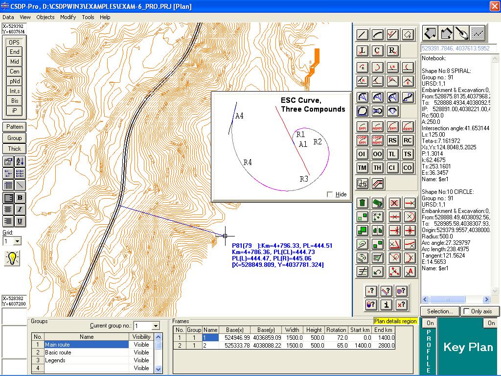
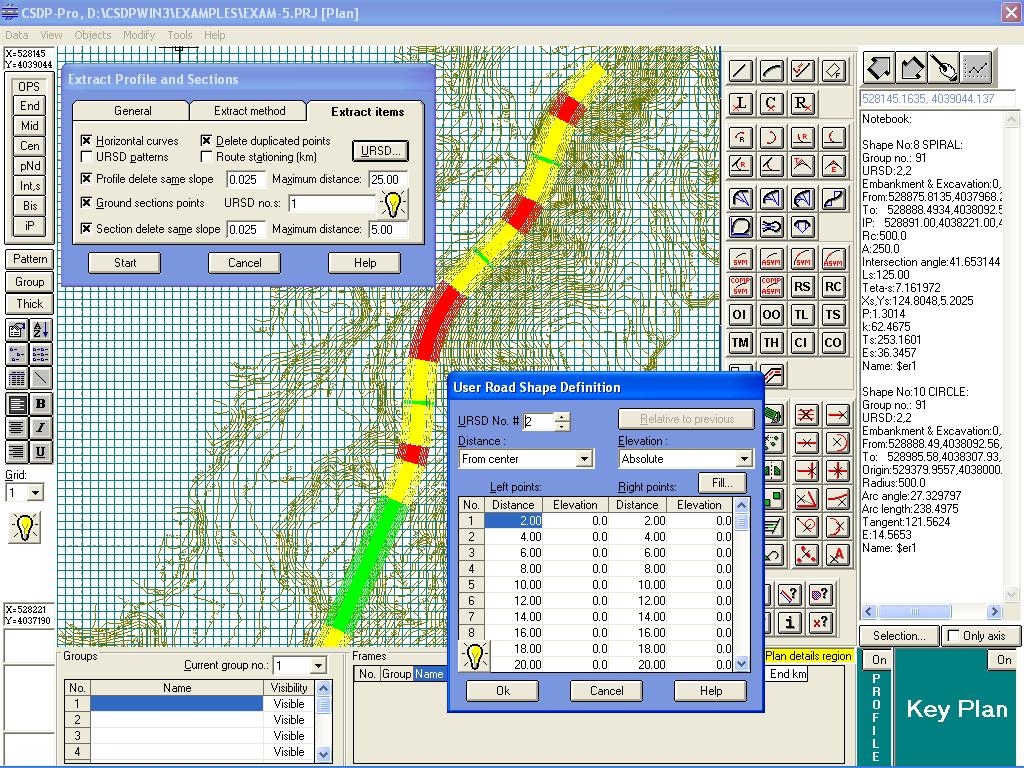
Plan mode in CSDP-Pro
- Semi-automatic design and calculation of two centered circular curves, three centered circular curves, and four centered circular curves
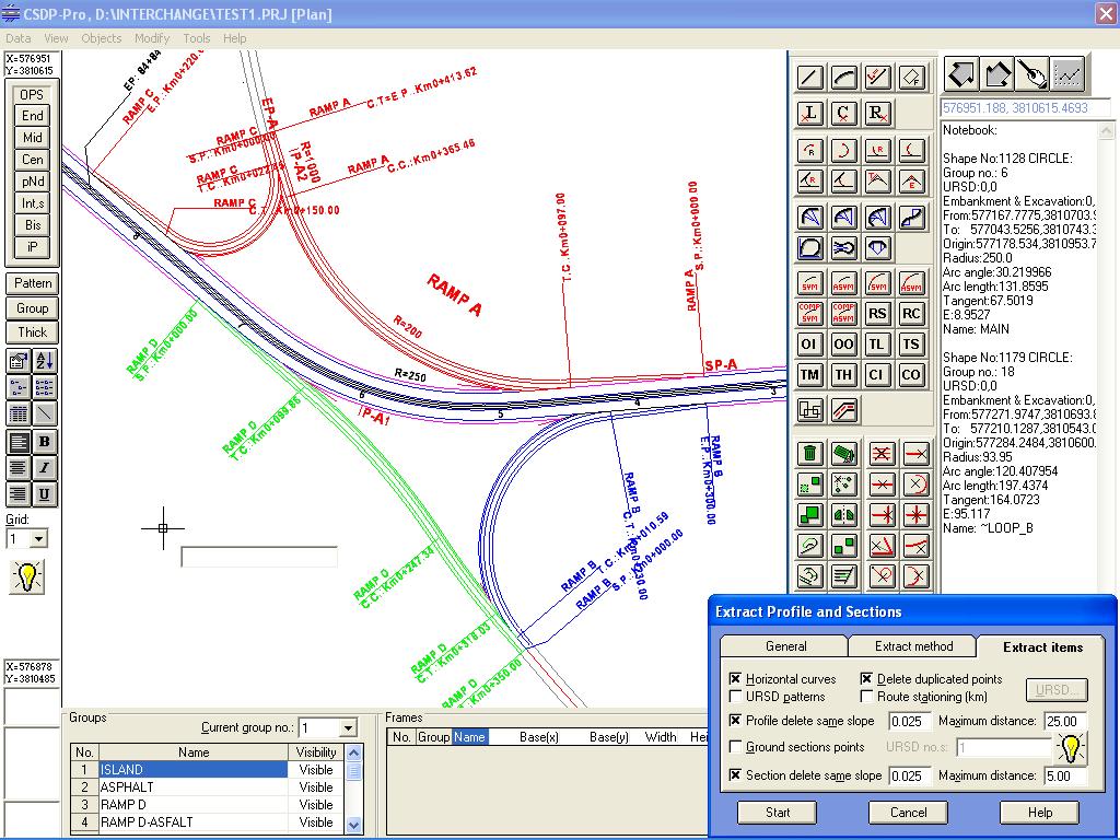
- Semi-automatic design and calculation of cloverleaf curves, and broken back curves
- Design and calculation of parabolic curves
- Design and calculations of symmetrical spiral curves, unsymmetrical spiral curves, and compound spiral curves
- Possibility to extract longitudinal profile and cross section shape of ground points along a route, by using TIN method (triangulated
Irregular Network) and an excluside method of CSDP, named as Contour Approach
- Possibility to define up to 16 bands at each side of the route center line
- Constructing topography map
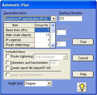
- Automatic drawing of horizontal alignment plan based on different components, such as spirals, circular curves, and parabolic curves
- Drawing of two centered, three centered, four centered, and reverse curves
- Drawing of cloverleaf curves in ramps and loops
- Extract of elevations of ground points along the route center line and cross sections based on either triangulated irregular network or contour approach methods
- Macro programming in plan mode, using CSDPMPL language
- Drawing and editing commands for CAD drafting purposes
- Import entities and points information from AutoCAD.
Plan mode in CSDP-Pro
|
| Back to Top |
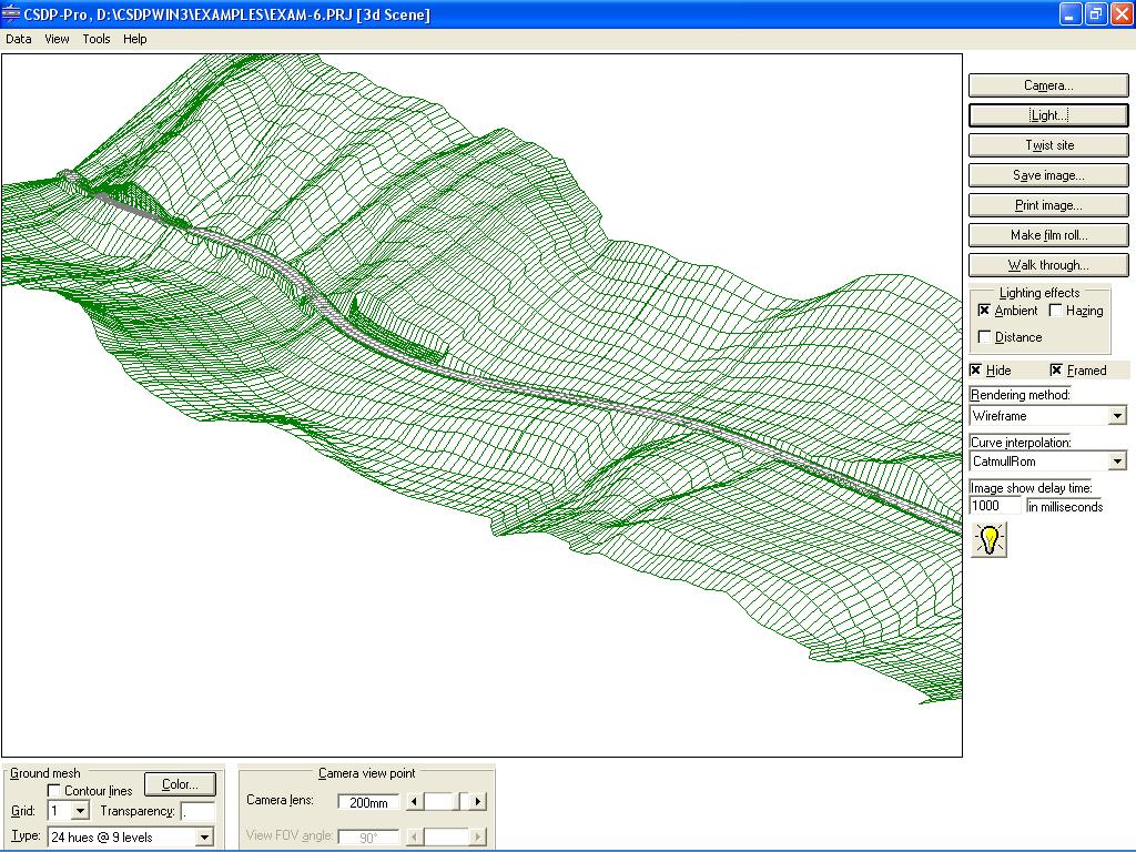
- The 3d scene environment having a scene, camera, and light source
to view the plan objects in spatial form
- Capability to define 3d objects for different components of
route, bridges, tunnels, building, tanks, etc.
- Possibility to control the location of the camera, along with
its focus point, lens, bank angle, etc.
- Showing the ground surface in a 3d form, using different mathematical
approaches like Bezier, BSpline, CatmullRom, Beta, etc.
- Possibility to control the light source (intensity level, color,
location, and focus point), along with controlling the ambient
light level and color, and using different effects of hazing, etc.
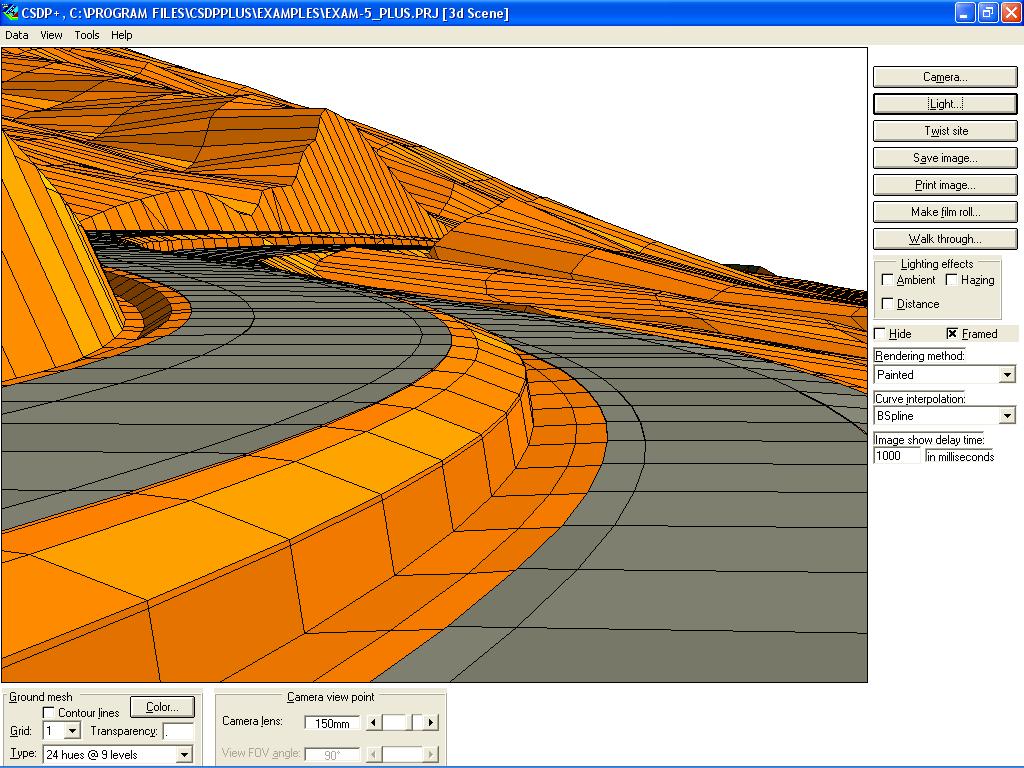
- Capability to show the 3d objects in three forms of mesh, painted,
and full rendered (FullZBuffer) and possibility to make the slides
- Capability to define the camera path for walk through, and preparing
slides to show them in sequentially like a movie.
- Possibility to save the 3d scene images either as bitmap files or Windows(TM) Metafiles.
- 3d Modeling of route and site for a 3d view
- Possibility to define different types of 3d objects such as bridge, tunnel, buildings, tanks, etc.
- Working camera with different lens and locations
- Using different methods of modeling as ground mesh, incorporating BEZIER, BSPLINE, Beta methods
- Working with light sources for rendering purposes
- Applying different rendering methods, wire framed, painted, and full rendering
- Possibility to create bitmap or windows metafile from scene images
- Walk through route and making AVI movie
|
| Back to Top |
|
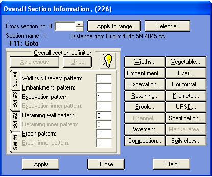
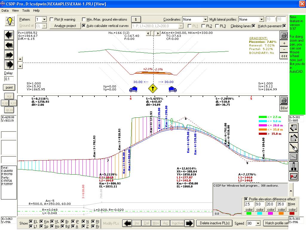
- Analysis of the longitudinal profile, up to three different
patterns for project lines
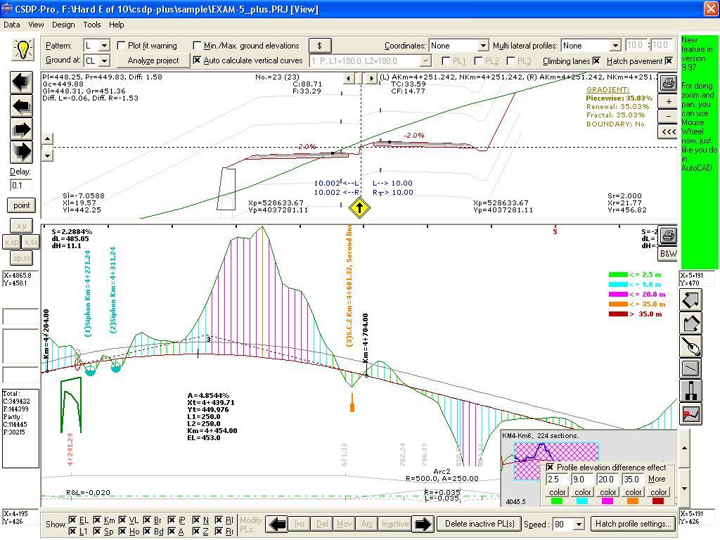
- Working with the longitudinal profile and cross section shapes graphically
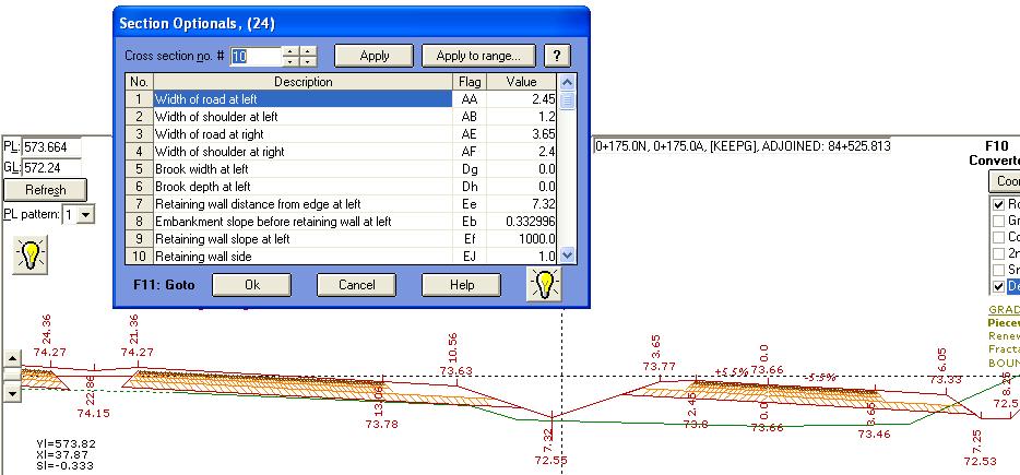
- Possibility to define different templates of cross section shape
for a route, including road band, shoulder and passage bands,
ditches, retaining walls, stairs (in excavation); up to 5 stairs
can be defined having different dimensions
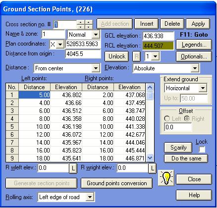
- Generation of new ground points along with respective cross
section shapes, by using surface linear gradient method
- Possibility to define different types of bridges along the route,
slab culvert, box culvert, slab bridge, siphon, arch culvert,
special bridge, overpass, etc.
- Up to three lines of project for analysis and comparison
- Graphical design of the longitudinal profile
- Real time calculation of volumetric calculations
- Checking of slopes, grades in longitudinal profile and cross sections
- Indicating icons for horizontal curves, bridges, and tunnels in cross section shapes
- Displaying of cross sections based on final shape and constructed shape
- Possibility to define vertical curves as circular and parabolic
- Automatic calculation of longitudinal profile of pipeline based on maximum allowable slope, and minimum ground elevation in right of way
- Possibility to define ditch in embankment and excavation conditions
- Possibility to define embankment slopes and up to five steps at each side
- Possibility to define excavation slopes and up to five steps at each side
- Possibility to define special kilometers for closing errors in form of gap or overlap
- Possibility to interpolate cross section shapes
- Possibility to define different types of bridges and drain pipes such as Siphon, slab culvert, box culvert, slab bridge, arch culvert, special bridge, infill slap bridge, and overpass
|
| Back to Top |
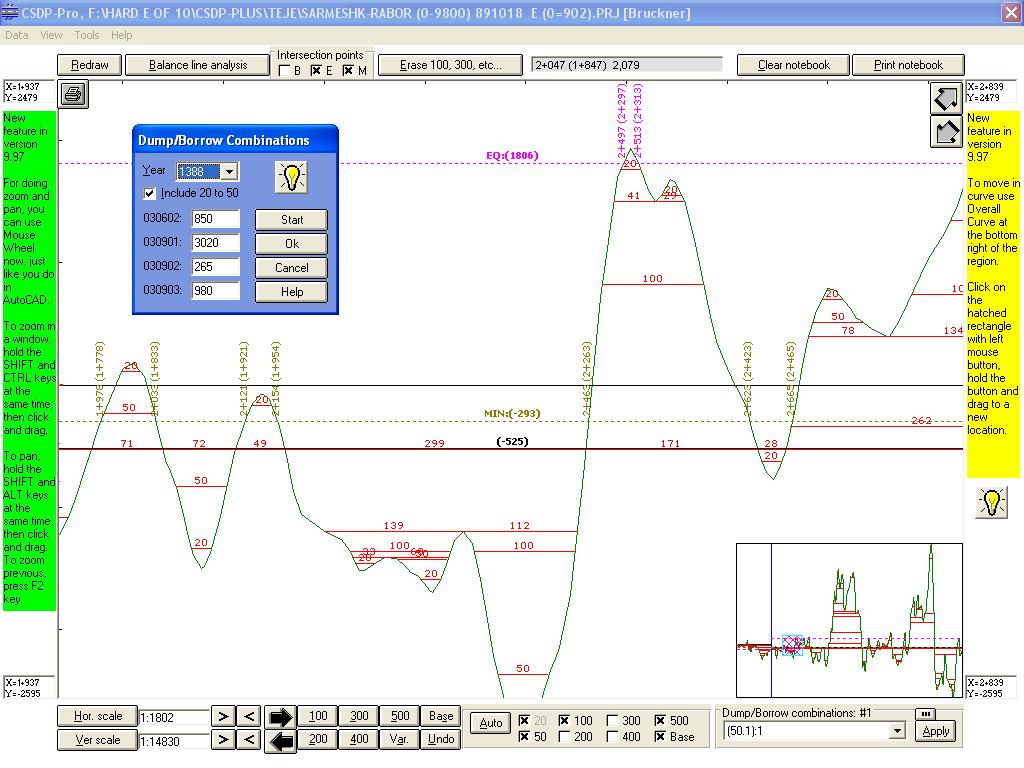
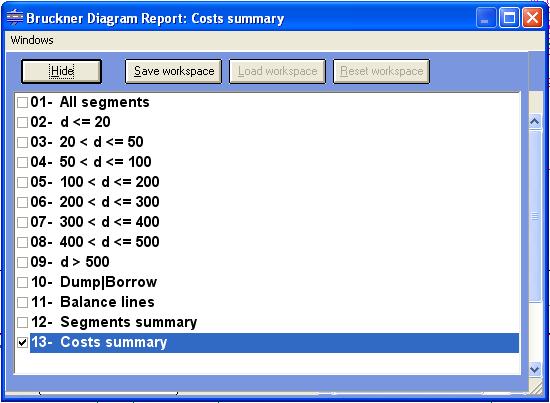
- Calculation of the bruckner curve points by considering the
cut and fill volumes, along with unsuitable cut volume, organic
soil (vegetable soil) volume, and the volume due to the settlement
of the soil after compaction
- Possibility to define up to 10 locations as the points of dumping or borrowing ground Possibility to define up to 20 lines of distribution
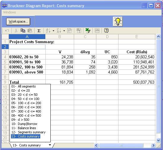
- Analysis and calculation of the carrying length of soil in categories
of less than 100 meters, 200 m, 300 m, 400 m, 500 m and more,
and calculation of total average carrying length.
|
| Back to Top |
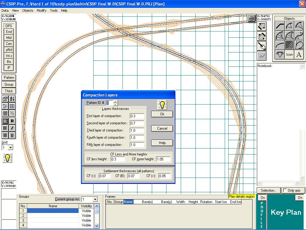
- Possibility to define up to 50 ground points at each side
- Possibility to define up to five different compaction layers (10 patterns)
- Possibility to define different layers of pavement, including Topeka, binder, black base, base, sub-base, and strengthening layer (10 patterns)
- Possibility to define organic soil (10 patterns)
- Possibility to define factors of soil shrinking and swelling
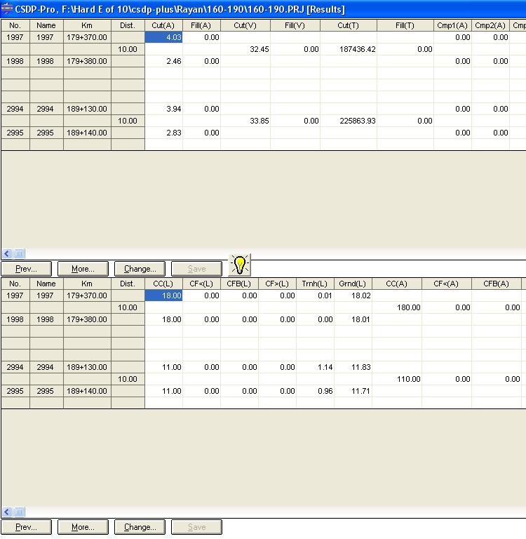
- Calculation of constructed volumes of cut and fill based on the progress of the project
- Calculation of volumes of final cut and fill volumes
- Calculation of volumes of different layers of compaction
- Calculation of areas under embankment condition
- Calculation of areas in excavation condition
- Calculation of volumes organic soil
- Calculation of different items of pavement layer
- Possibility to export calculated volumes and areas to Microsoft Excel for cost-estimate analysis
|
|