Rah AFzar Tarh
Company overview
Products
Contents
Training Videos
Free Stuff
Site Map
Contact us
Support services
Home page
|
- Possibility to have profile at edges instead of center line along with corrections to be made for the kilometers
- Possibility to print project line elevations at edge of the route in printing plan shape
- Possibility to export a data file of xyz points for project line at center and edges having specific codes that can be imported to CSDPMAP application software
- Possibility to specify color and size of points used to show extracted cross sections in Plan mode
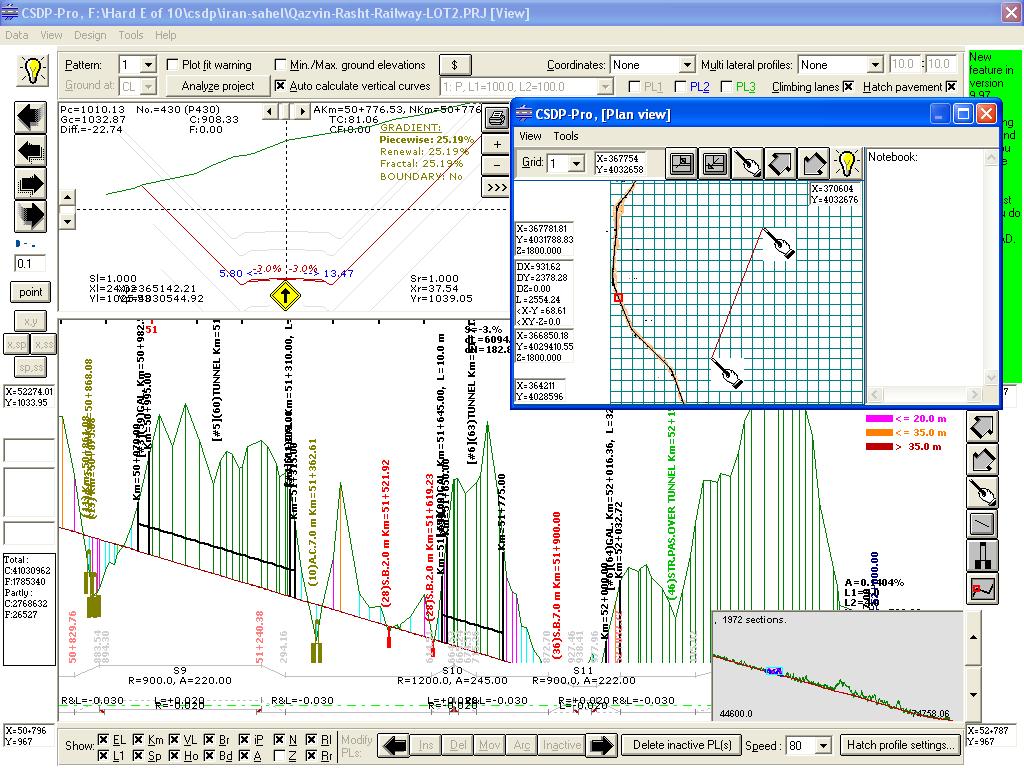
- A new window in Profile and Sections mode that can be used to see routes plan at the same time, named as Plan view window
- A new embankment case named as D for height consideration at center instead of at edge
- Increasing number of radius-dever table from 20 to 40 radiuses
- Possibility to make overall profile region visible or invisible in Profile and Sections mode
- Possibility to specify a Side property for bridges when using Extended highway template type
- A new property for horizontal arcs to categorize arcs to affect only on devers (lateral slopes), only on curves (horizontal alignment) or both (the default)
- Possibility to specify line thickness and color for special bridges and tunnel in longitudinal profile output
|
|
- A new tool named as Goto F11 key, in some dialog boxes such as Ground Section Points, Bridges, etc. to move between items based on the specified distance from origin (kilometer of the item)
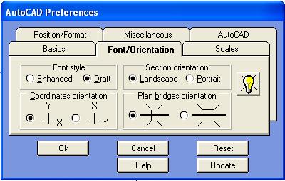
- Possibility specify bridge orientations when printing route's plan
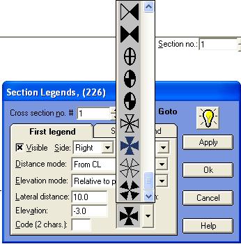
- Possibility to assign section legends when displaying or printing section shapes
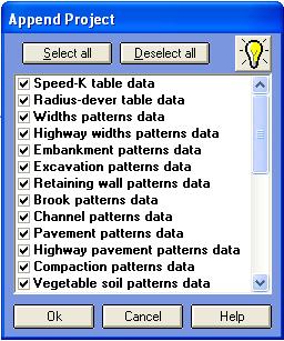
- A new dialog box for appending other projects to current project
- A new type for gallery in Bridges/Tunnels Specifications dialog box
- Possibility to get information about structures like tunnels, galleries, special bridges, retaining walls in Full Reporting
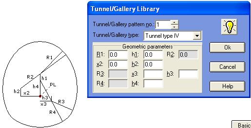
- A new dialog box named as Tunnel/Gallery Library to define different types of tunnels/galleries
|
| Back to Top
|
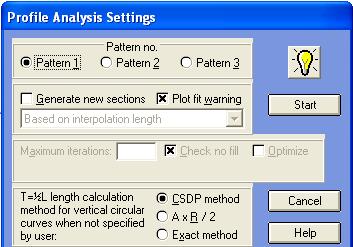
- Possibility to create and interpolate new cross sections at specific kilometers while analyzing longitudinal profile with Profile analysis option
- Mousewheel can be used for zoom and pan operations in Plan mode and Profile and sections mode
- Possibility to specify maximum algebraic sum of devers (lateral slopes) of main band and shoulder band with respect to Standards (default of 0.08%)
- A new excavation case for berm (stair) at top with a new shape
- A new criterion in pipe line analysis named as minimum segment length
- Possibility to have pavement shape in form of Offset in all profile types
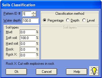
- Possibility to have soil classification (mud, soft, hard, rock and rock with explosives) with three methods of percentage, depth, and level methods
- Possibility to change elevations mode of cross sections from Absolute to Relative to center and or Relative to previous and vise versa
- Possibility to have different pavement patterns for left and right side of the route
- A new layout type for profile layout of pipe line projects
|
- Possibility to print project elevations at edge instead of center line in longitudinal profile output
- A new tool named as IntelliMouse for flying over the route in Plan mode
- Possibility to choose which parameters of horizontal arcs to be included when printing plan layout
- Possibility to have multiple groups for different items of a routes plan when using Automatic plan optionPossibility to choose which parameters of horizontal arcs to be included when printing plan layout
- Possibility to have multiple groups for different items of a routes plan when using Automatic plan option
- Increasing number of cross section points when extracting from 15 to 48 at each side and possibility to delete those points having almost same slope
|
|
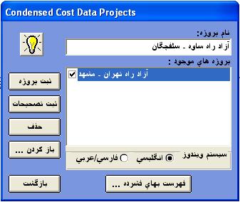
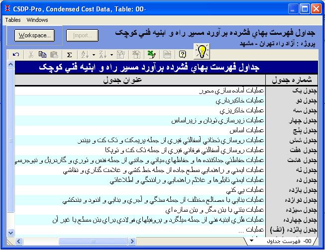
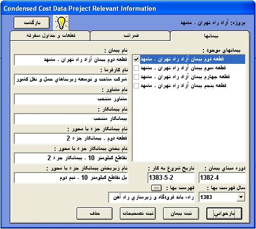
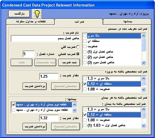
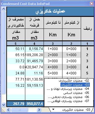
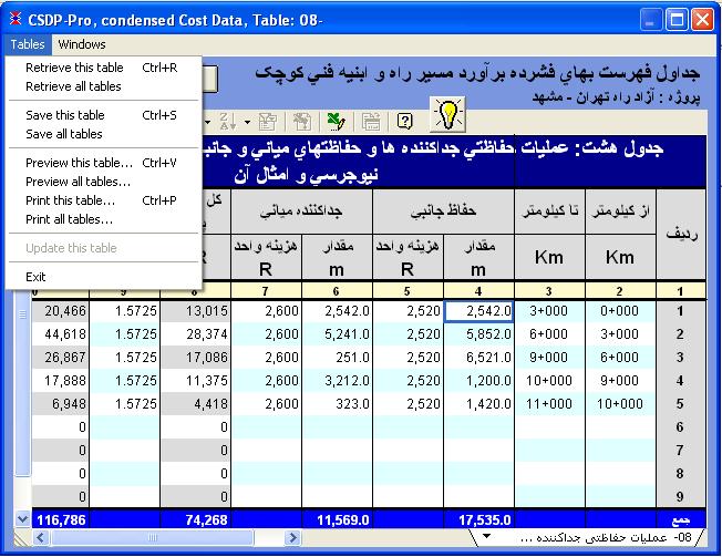
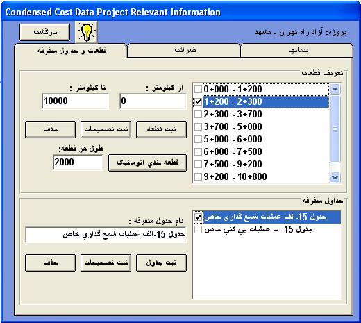
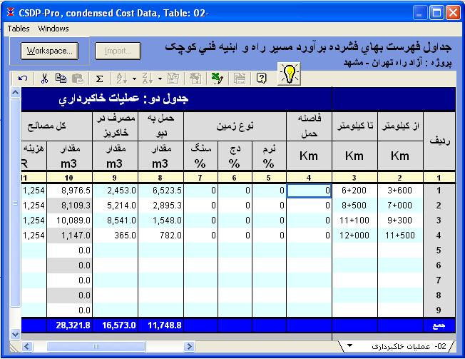
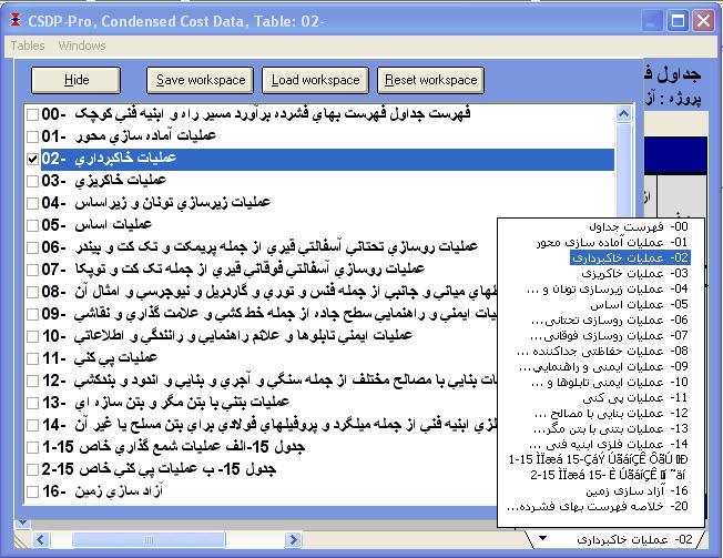
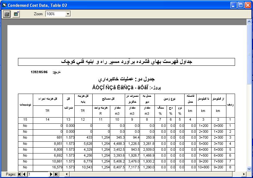
- New options to have condensed cost data tables for area and length items
|
| Back to Top
|
- Possibility to combine different area and length items to create new formulas
- Possibility to display distinguished section names, and zones in Profile and Sections mode
- Possibility to define project lines graphically in Profile and Sections mode with two new methods named as x,ss and sp,ss
- Possibility to place shoulder band after passage band in Urban template
- Two new algorithms to construct embankment edge slopes
- Possibility to apply brook depths by two methods of Fixed and Variable
- Possibility to combine URSD patterns with normal Widths and Devers pattern to create new section templates
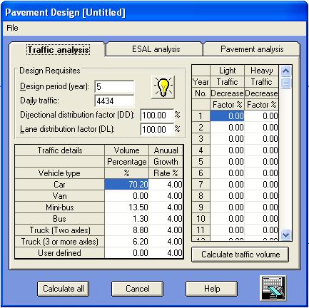
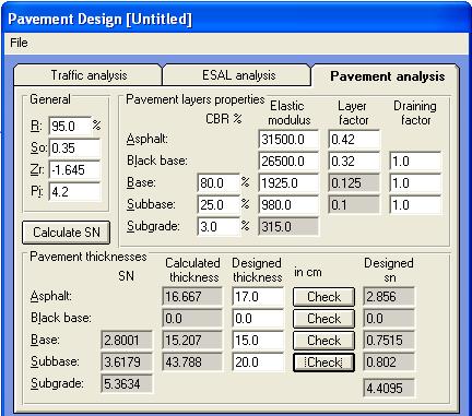
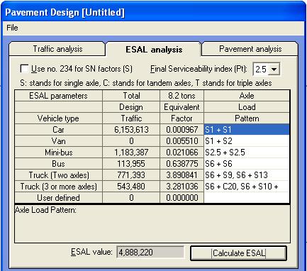
- Pavement design by Standards 234, and AASHTO standards
- Possibility to copy ground points, second ground points, constructed points from one set to the other
- Possibility to have multi-lateral profiles at points corresponding to specific points in cross section template along with elevations, corrected distances, lateral distance, etc.
- A new profile layout for pipe-line projects
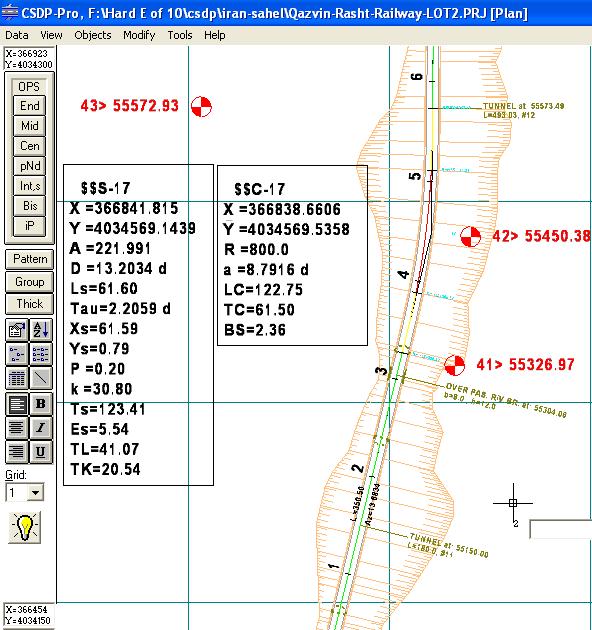
- Possibility to display bridges, bench marks, boundary slopes, and horizontal arcs information in Plan mode and in Plan view
- Possibility to model different types of serpentine curves in Automatic Plan
|
- Increasing maximum number of survey points that can be worked with in extracting profile and sections from 9 million to 100 million points, and using much quicker algorithm for extracting
- Increasing number of cross section points at each side form 48 to 99 points
- Possibility to have longitudinal profiles of constructed sections, and three project line patterns at the same time with normal longitudinal profile
- Possibility to display retaining walls in Profile and Sections mode and in Plan mode
|

|
|
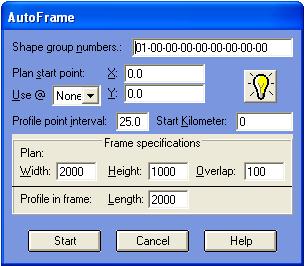
- A new Auto-frame feature to create plan-profile frames for existing plan automatically
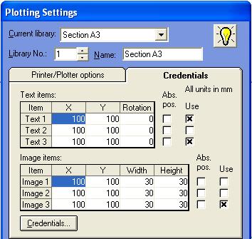
- Direct plotting/printing of cross sections, longitudinal profiles, and plan-profile
- Possibility to create MDI and PDF files of cross section shapes, longitudinal profile, and plan-profile
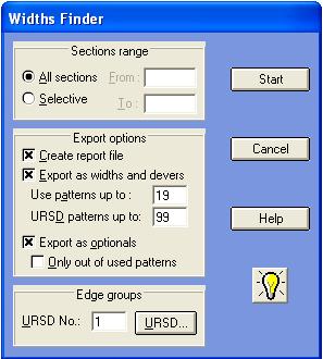
- A new Widths-finder tool in Plan mode, to calculate required widths of different bands in a template based on the plan shape of the route
|
|
|
|