Rah AFzar Tarh
Company overview
Products
Contents
Training Videos
Free Stuff
Site Map
Contact us
Support services
Home page
|
- Possibility to create and interpolate new cross sections at specific kilometers while analyzing longitudinal profile with Profile analysis option
- Mousewheel can be used for zoom and pan operations in Plan mode and Profile and sections mode
- Possibility to specify maximum algebraic sum of devers (lateral slopes) of main band and shoulder band with respect to Standards (default of 0.08%)
- A new excavation case for berm (stair) at top with a new shape
- A new criterion in pipe line analysis named as minimum segment length
- Possibility to have pavement shape in form of Offset in all profile types
- Possibility to have soil classification (mud, soft, hard, rock and rock with explosives) with three methods of percentage, depth, and level methods
- Possibility to change elevations mode of cross sections from Absolute to Relative to center and or Relative to previous and vise versa
- Possibility to have different pavement patterns for left and right side of the route
- A new layout type for profile layout of pipe line projects
|
|
|
- Possibility to print project elevations at edge instead of center line in longitudinal profile output
- A new tool named as IntelliMouse for flying over the route in Plan mode
- Possibility to choose which parameters of horizontal arcs to be included when printing plan layout
- Possibility to have multiple groups for different items of a routes plan when using Automatic plan option
- Increasing number of cross section points when extracting from 15 to 48 at each side and possibility to delete those points having almost same slope
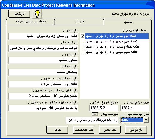
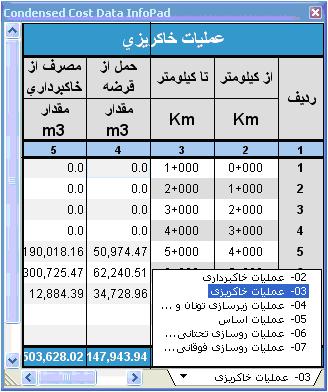
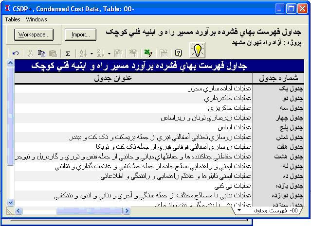
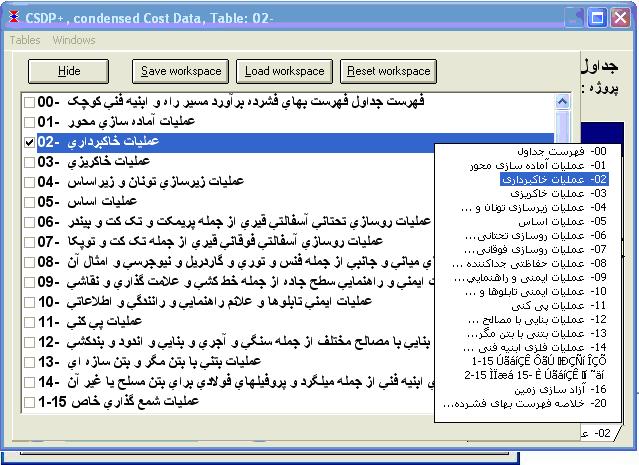
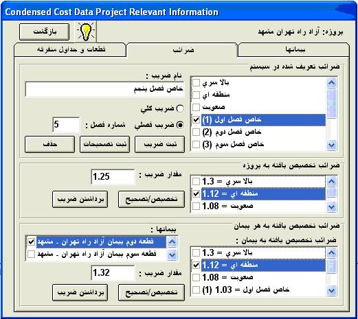
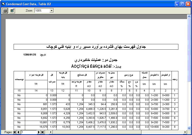
- New options to have condensed cost data tables for area and length items
|
|
|
| Back to Top
|
- Possibility to combine different area and length items to create new formulas
- Possibility to display distinguished section names, and zones in Profile and Sections mode
- Possibility to define project lines graphically in Profile and Sections mode with two new methods named as x,ss and sp,ss
- Possibility to place shoulder band after passage band in Urban template
- Two new algorithms to construct embankment edge slopes
- Possibility to apply brook depths by two methods of Fixed and Variable
- Possibility to combine URSD patterns with normal Widths and Devers pattern to create new section templates
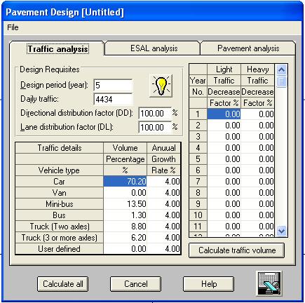
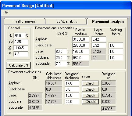
- Pavement design by Standards 234, and AASHTO standards
- Possibility to copy ground points, second ground points, constructed points from one set to the other
- Possibility to have multi-lateral profiles at points corresponding to specific points in cross section template along with elevations, corrected distances, lateral distance, etc.
- A new profile layout for pipe-line projects
- Possibility to display bridges, bench marks, boundary slopes, and horizontal arcs information in Plan mode and in Plan view
|
| Back to Top
|
- Possibility to model different types of serpentine curves in Automatic Plan
- Increasing maximum number of survey points that can be worked with in extracting profile and sections from 9 million to 100 million points, and using much quicker algorithm for extracting
- Increasing number of cross section points at each side form 48 to 99 points
- Possibility to have longitudinal profiles of constructed sections, and three project line patterns at the same time with normal longitudinal profile
|
- Possibility to display retaining walls in Profile and Sections mode and in Plan mode
|
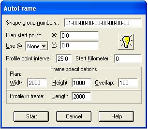
- A new Auto-frame feature to create plan-profile frames for existing plan automatically
- Direct plotting/printing of cross sections, longitudinal profiles, and plan-profile
- Possibility to create MDI and PDF files of cross section shapes, longitudinal profile, and plan-profile
|
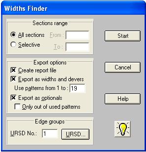
- A new Widths-finder tool in Plan mode, to calculate required widths of different bands in a template based on the plan shape of the route
|
|